SECTION 1: INITIAL MODULE ASSMBLEY
These modules should be assembled on a bench before mounting on the vertical breadboard. Assembly of the modules can be done in any order.
Entrance beam expander: EntranceBeamExpander_4x1

1) Mount the Thor_ACN254-050-B:1 lens in its lens tubes ensuring that its curved sides will point inwards when assembled.

2) Assemble the cage from thorlab parts including Thor_AC254-200-B-ML mounted lens. Set the lens cage plates approximately 141mm apart. The exact position of the plates will be set during microscope assembly.

Remote focus mirror positioner: RFAMirrorAssemb_EquipSolLFA2004
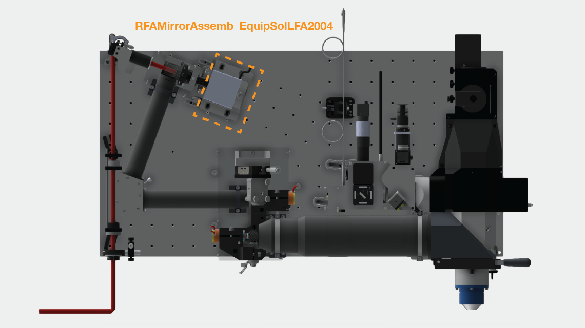

1) Gather parts for mounting the mirror on the voice coil bobbin. Clean the mirror mounting screw 90666A101_TYPE 316 SS LOW PROFILE SOCKET HEAD CAP SCREW with drop of methanol. Place small drop (30 ul) of lock-tight onto threads on the voice coil bobbin. Screw in screw, and leave overnight to set.

2) Glue remote focus mirror onto the screw using 1-day epoxy. Fill hole on top of screw with epoxy and then mount mirror centered on the screw head (slight deviations from the center of the screw head are fine).

3) Assemble the voice coil base and mount voice coil


***INSERT PHOTO OF FINISHED ASSEMBLY***
Fold mirror assembly: FoldMirrorAssemb
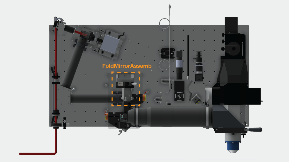

1) Attach translation stage to the FoldMirrAssembBracket.
2) Attach McMassterCarr standoff to FoldMirrAssembBracket
3) Attach gimbal mount to translation stage via adaptor plate.4) Adjust thickness of gimbal mount to 29.7 mm. The knob in the bottom corner should no longer be adjusted. Mark it with a red X to ensure it doesn't accidentally get changed during the setting of the compensators.
***INSERT PHOTO OF RED X on gimbal***
5) Cement the fold mirror centered to mirror blank (non-frosted side). Using norland 81. The mirror blank then fits inside the mount on the gimbal.
***Describe gluing procedure ***
***INSERT PHOTO OF FINISHED ASSEMBLY***
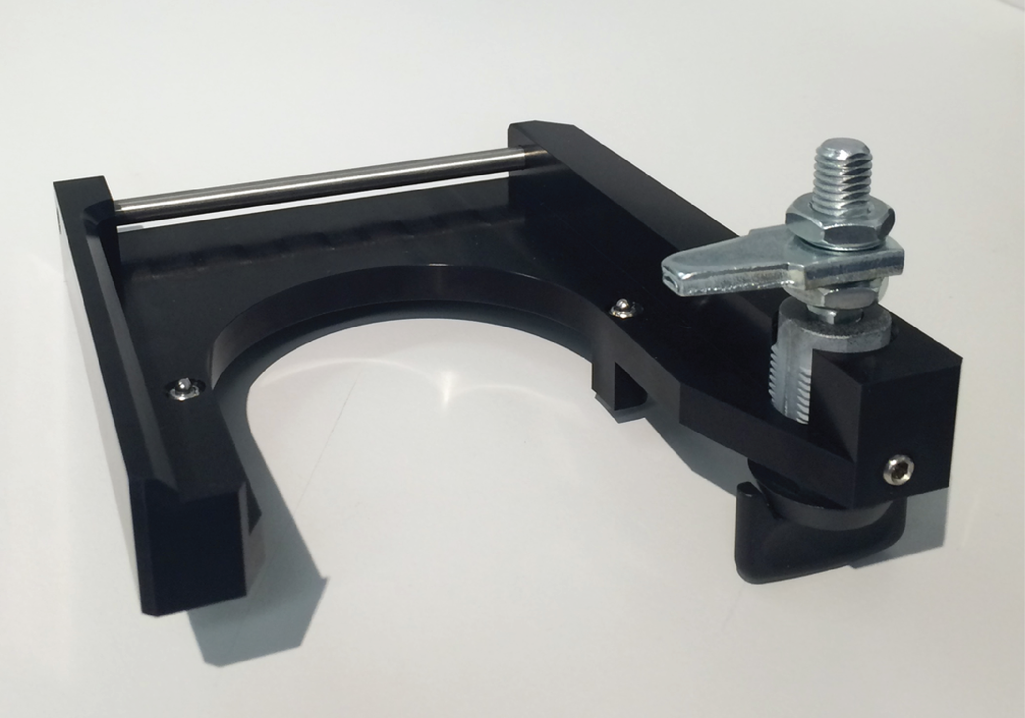
Imaging objective tray: IMOTrayAssby
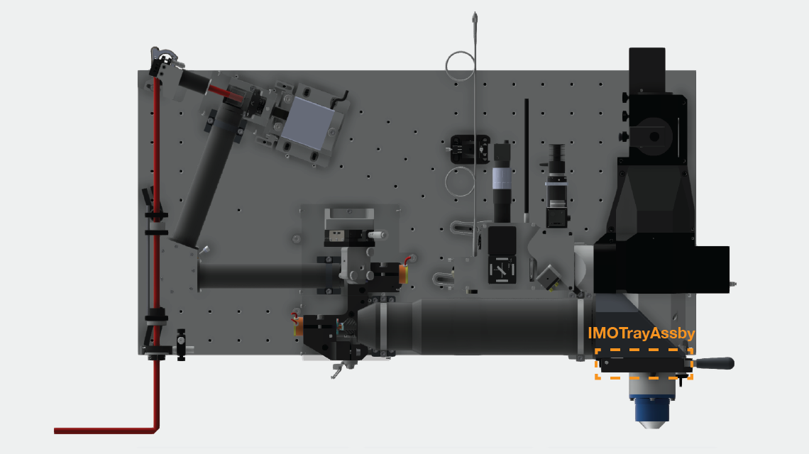
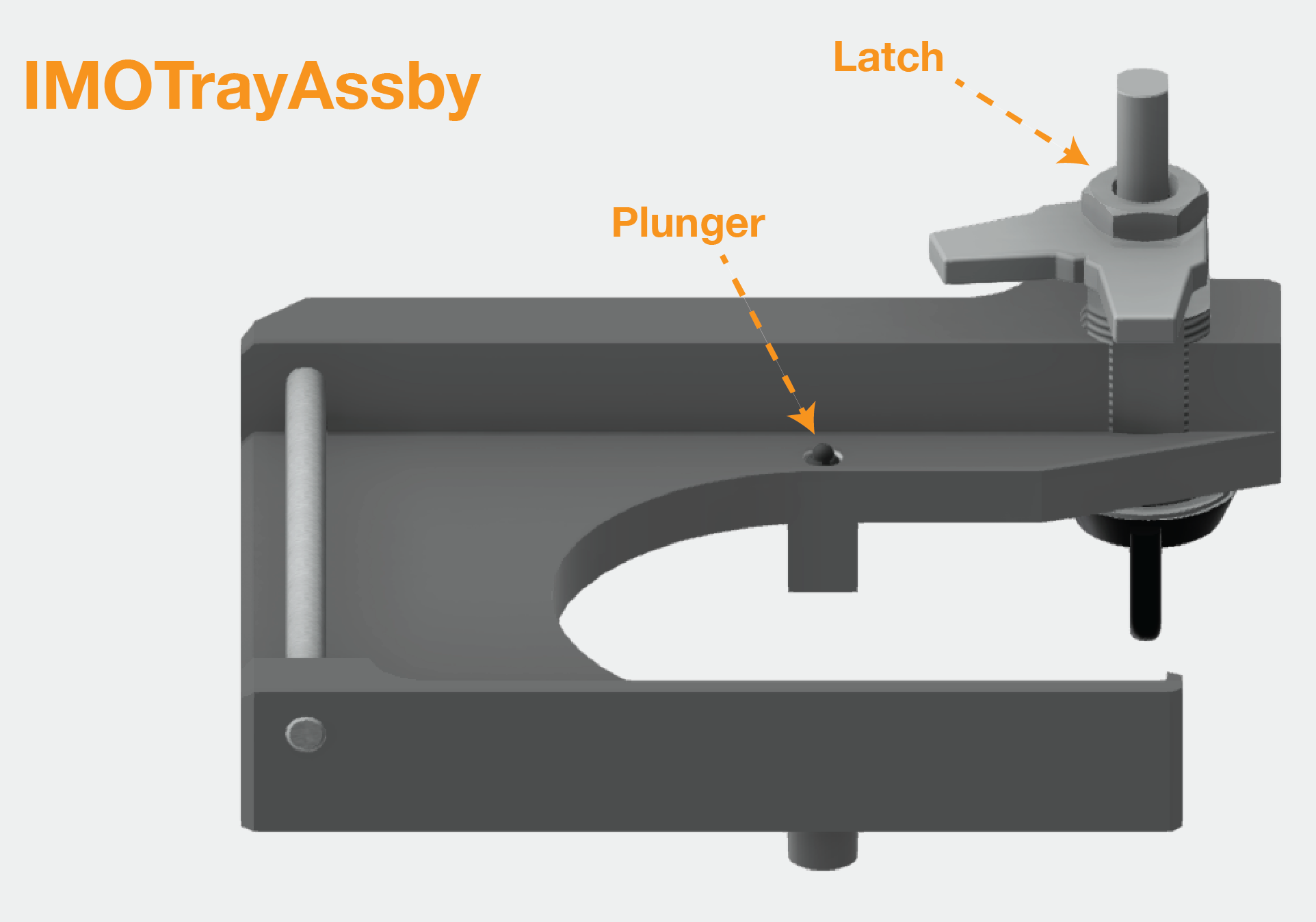
1) Set to of plunger to be flush with the metal surface of the tray
2) Slide dowel rod in place
3) Assemble latch, making sure orientation is correct when the latch is fully closed and open. The exact height of the latch will be set during final assembly.
Big detection lens and accessory optics dichroic holder: BigDetLensHolderAssby
...