- Set laser to central wavelength, 970 nm
- Manually adjust pockels to about so beam is just bright enough on card to see
- Check beam is still passing through irises of PPC in bypass mode
- Adjust angle of prism such that beam passes through center of exit iris
- Direct beam into bottom of table periscope, through an iris on the table and the iris on the bottom of the periscope
- Add the quarter waveplate before the gantry periscope on the table, Set it 45° to the fast axis to make the polarization circular going into the gantry periscope.
The gantry system translates the microscope along 3 axes (X,Y,Z) and rotation (θ). Ideally, the beam should not deviate during movement of any of the four translations. Any movement results in a deviation of the beam onto the back aperture objective and consequently affects the scanned image. Therefore, a multi-mirror periscope which consists of 6 mirrors (See picture below) was engineered in order to allow sufficient control of the beam alignment onto the vertical breadboard. Completion of this alignment defines the beam propagation on the vertical breadboard to which all vertical breadboard optics should be aligned to.
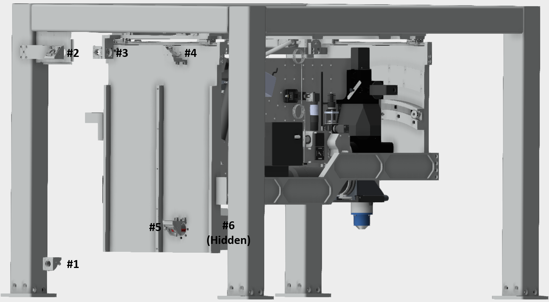
Coarse alignment of gantry periscope: The first step is a coarse alignment, this just ensures that the beam is roughly going through the center of each of the six periscope mirrors. This safeguards that the beam won’t clip on the housing when fine adjustment commences.
-Adjust the last two mirror from the prism compressor such that the beam is parallel to the plane of the table and hits periscope mirror #1 at 45° directing the beam up to periscope mirror #2.
-Adjust the knobs on periscope mirror #1 such that the beam is roughly centered on periscope mirror #2
-Adjust the knobs on periscope mirror #2 such that the beam is roughly centered on periscope mirror #3
-Adjust the knobs on periscope mirror #3 such that the beam is roughly centered on periscope mirror #4
-Adjust the knobs on periscope mirror #4 such that the beam is roughly centered on periscope mirror #5
-Adjust the knobs on periscope mirror #5 such that the beam is roughly centered on periscope mirror #6
It is essential that the beam does not deviate when any of the four translations of the gantry are moved. In order to confirm this property each axis must be tested and aligned individually. While one could monitor the deviation coarsely by eye for fine alignment a digital readout is essential. Therefore, it is best to use a camera, beam profiler or position sensitive detector to monitor beam deviations.
Place the sensor far away from the periscope. Ideally, this sensor is placed after the remote focus and objective jig. **At this point the telescope, remote focus objective and voice coil should be removed. Use the vertical breadboard periscope to roughly center the beam through both irises from the jig onto the center of the detector. This large separation ensures any small beam deviation will result in a detectable change in the position on the sensor. First, start the gantry to one extreme of its travel and note the location of the beam on the sensor. Next, move the gantry to the other extreme and record its position on the sensor. If the input beam is perfectly aligned to the axis of travel the two positions should not change. In practice some difference will always be observed albeit small since the alignment is limited by the linearity of travel along the axis.
A particular axis alignment is controlled by a specific periscope mirror for linear axes X, Y and Z and 2 periscope mirrors for rotation. These relationships were defined by how the mirror mounts are attached to the gantry. Consequently, there is a particular order and a specific beam alignment to how the periscope is aligned to the mounted breadboard. The order is as followed;
-Periscope mirror #2 for Y axis.
-Periscope mirror #3 for X axis.
-Periscope mirror #4 and #5 for rotation.
-Periscope mirror #6 for Z axis.
- Move gantry system back and forth in y. Adjust top mirror on periscope gantry such that the beam remains stationary on the camera.
- Move gantry system back and forth in x. Adjust first mirror inside box (high up) such that the beam remains stationary on the camera.
- For rotation need to control four degrees of freedom, so have to move camera between two locations on the vertical breadboard (near) and (far, where it is now). The second location is ideally where quarter waveplate goes (near camera). Have to keep beam centered on both. First keep centered on near camera using far mirror, the one that comes next after one used for x, (high up and closer to vertical breadboard). Then keep centered on far one using mirror at bottom of gantry to keep centered on far one. Watch beam move on camera during move, use mirrors to adjust beam position to be at the center of the curvature of the circle traced out by the beam. THIS CAN BE QUITE TIME CONSUMING - IN PART BECAUSE THE GANTRY ANGLE HAS TO BE MOVES BACK AND FORTH.
- Aligned z axis using mirror inside the rotation bearing, keeping beam constant on the camera in the far position.
- All alignments for each axis is iterative. Therefore, it might take multiple iterations before acceptable alignment is achieved. Successful alignment requires patience.
- Add in the other quarter waveplate, set to minimum reflection (maximum transmission) through polarzing beam splitter. Put the card to look at the reflected beam and make it as dim as possible.
- Add in the beam expander. There is an iris on the front. Position so that beam goes through it with the whole assembly centered.
- Move the entire beam periscope assembly such that the beam is centered on two periscope mirrors. Align periscope through the two irises on the remote focus jig and into the camera using the two translation stages (which should produce pure translation).
- Mounting the voicecoil. Remove the remote focus objective so that you don't accidentally damage it. The dowel pins are used to guide the voice coil assembly during mounting, but the exact position of the assembly is set using the nudgers. The lateral position of the beam is adjusted by changing the angle of the voice coil assembly with the two nudgers. Do this while looking at the back reflection on a card near the entrance to the large bearing. The yaw position of the beam is then adjusted by tipping the voice coil assembly. This procedure ensures the mirror is perpendicular to the beam. Look at the beam back near where the quarter waveplate. If you ever see a beam on the card then you know you aren't aligned.
- Once the voice coil mirror is aligned remove the voice coil and add remote focus objective back on.
- Now set the z position of the voice coil mirror. Add the voice coil back onto the rig
Multistage periscope alignment
Quarter wave plate adjustment for multistage periscope
Alignment of beam to remote focus objective
Adjustment of quarter wave plates for maximum transmission
Alignment of RF mirror assembly
Alignment of beam to imaging objective using compensators
Adjustment of galvo voltage divider gain
Overview
Content Tools