Assembling compressor
Assemble the retroreflector carriage
1) Mount the AP90RL large angle bracket on the XT95P11 carriage.
2) Attach the TSX-1D stage to the AP90RL large angle bracket.
3) Use two M6 12mm screws to attach Thor_BA2F to retroreflector.
4) Attach the RS1:4 to the TSX-1D stage with a set screw.
5) Slide the BA2F onto the RS1:4. Adjust the orientation such that when the beam enters the retroreflector it will be reflected up without hitting an edge.
Assemble the 2x beam expander
1) Attach the SM1D12D ring iris to the GBE02-B 2x beam expander, making sure it is on the correct end.
2) Attach the SM1RC lens tube rings to the TR-05:4 posts and put them in the UPH3 universal post holders.
3) Slide the beam expander into the lens tube rings and tighten them
Assembling the prism pair compressor
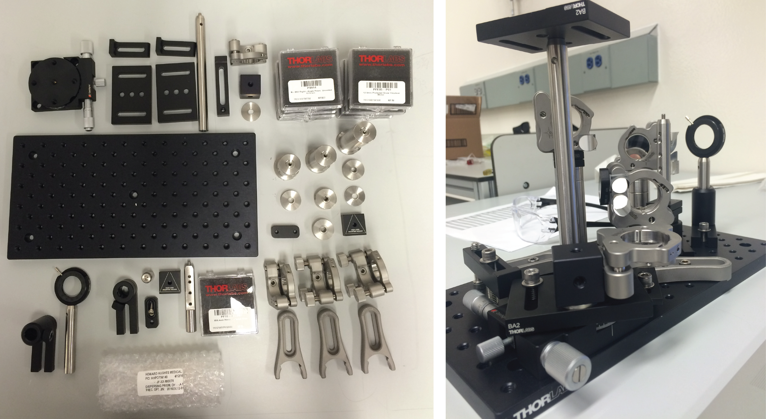
Several gluing and customization jobs are required
1) Gluing job 1. Glue prisms to TRT3 post with cutout using norland 81 UV cure glue. First glue the bottom prism, flush to the top surface of the post cutout, and positioned at a right angle. Put a few drops of UV cure glue on post and place prism on top. Do this inside a V-block to ensure the angles are correct. Once the bottom prism has been glued down, glue to top prism at a distance of 39.3mm (between outside faces). Then glue mirrors to prisms. Hold the post in vice at correct orientation, place UV cure glue on prism and glue down mirror. Rotate post to glue second mirror.

2) Attach the TRT3 post of the top plate of the KB1X1 kinematic mount using an AE8E25E internal to external 1/4 to 8/32 thread adapter. Unfortunately the length of the thread adapter needs to be shortened by about two threads to let it fit inside the TRT3 post. We did this using a grinder. If anyone can find a shorter version of Thorlabs AE8E25E that would be great (inner thread, 8/32; outer thread, 14 - 20).

3) Assemble the bottom half of the kinematic mount with the KMCP plate and the TR1 post and UPH1 post holder. The bottom plate of the kinematic mount should be positioned in the KMCP plate such that the mirrors attached to the TRT3 post are on axis with the TR1 post. This happens when the bottom plate of the kinematic mount is pushed almost flush towards the near end of the KMCP plate.

4) Gluing job 2: Glue single mirror and prism to polaris mirror mount, making sure orientation of both are correct. The side and back of the prism should be flush with the edges of top part of the mount.

3) Attach this mirror mount to the top of the KB1X1 kinematic mount using a 8-32 screw and a nut.
4) Gluing job 3: Glue two mirrors and prisms to K1-2AH polaris mount (without thumb screws). First attach KCP2 centering plate to polaris mount. Glue one prism directly to the mount, flush with edge of the bottom part of the mount and with its back face 15.6 mm from the end of the top piece of the mount. You can use the KCP2 to align the prism with the edge of the bottom of the mount as shown below (the caliber measures the 15.6 mm distance).

Then glue the other prism to the KCP2 centering plate so that it is aligned with the prism already glued. Note the positioning of the KCP2 piece. This is the final position. Make sure that the mounted prism has some space to move wrt to the edge of the KCP2.

Make sure the side of the prisms are both aligned to each other and the side of the polaris mount. There should be a 1 mm space between the two prisms, AND a 1 mm gap between the back face of this second prism and the mount. You can use washers as spacers (see below).


5) Attach one polaris mount to the RM1F cube. Attach this cube with the RS2M spacer to the BA2 baseplate, making sure the cube is orientated such that the corner of the polaris mount is over the center of the BA2. Attach the BA2 to the Optosigma rotation stage, sliding the BA2 so the end of the slots is flush against the screws.
6) Secure the optosigma to the breadboard such that it is 25.3 mm from right side and 2.5 mm from top side.
7) Secure posts with polaris mounts to breadboard, matching the location of the items with their approximate locations in the breadboard. Ensure that the mirror, prisms all lie on the same axis.
8) Set the height of the KMCP to be 46.0 mm above the breadboard.
9) Gluing job 4: Glue custom prism onto polaris mount. Use norland 81. There are two polished and one un-polished side. Note prism is not an equilateral triangle. Make one side flush with polaris mount, and tip flush with other edge of mount.
10) Set the height of top of the iris holding posts to 87.0 mm
3 Comments
Natalia Orlova
Hi. Can someone please post a few close-up pictures of the entire compressor assembled as well as the modules: prism and the assembly that holds it, etc? Thank you! Natalia
Unknown User (sofroniewn)
Hi Natalia
I have put a dropbox link to all the photos I took in preparation for the workshop, they are only very roughly organized, but they should have some closeups of the compressor in there. I can also go through them if you can't find any, just let me know. The link is on the main page of the documentation. Feel free to add any good photos to any of the documentation pages
Best
Nick
Natalia Orlova
Thanks, Nick. I also realized right after I posted this that there's a CAD model of the PPC. That answered all my questions.
Natalia