SECTION 1: INITIAL MODULE ASSMBLEY
These modules should be assembled on a bench before mounting on the vertical breadboard. Assembly of the modules can be done in any order.
Entrance beam expander: EntranceBeamExpander_4x1

1) Mount the Thor_ACN254-050-B:1 lens in its lens tubes ensuring that its curved sides will point inwards when assembled.

2) Assemble the cage from thorlab parts including Thor_AC254-200-B-ML mounted lens. Set the lens cage plates approximately 141mm apart. The exact position of the plates will be set during microscope assembly.

Remote focus mirror positioner: RFAMirrorAssemb_EquipSolLFA2004
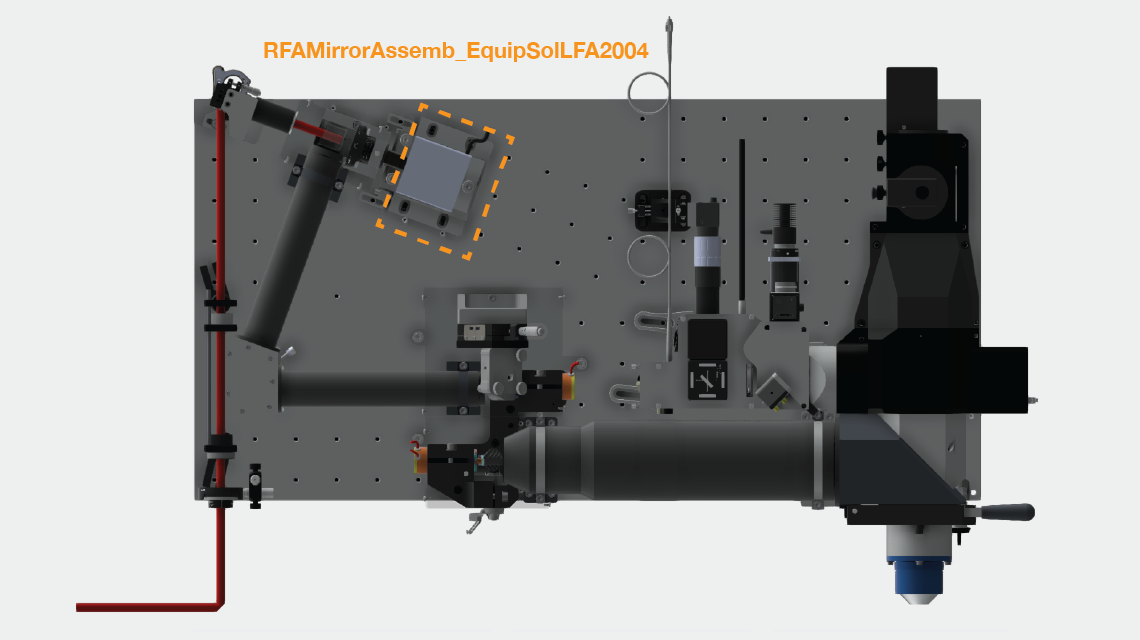

1) Gather parts for mounting the mirror on the voice coil bobbin. Clean the mirror mounting screw 90666A101_TYPE 316 SS LOW PROFILE SOCKET HEAD CAP SCREW with drop of methanol. Place small drop (30 ul) of lock-tight onto threads on the voice coil bobbin. Screw in screw, and leave overnight to set.

2) Glue remote focus mirror onto the screw using 1-day epoxy. Fill hole on top of screw with epoxy and then mount mirror centered on the screw head (slight deviations from the center of the screw head are fine).

3) Assemble the voice coil base and mount voice coil


***INSERT PHOTO OF FINISHED ASSEMBLY***
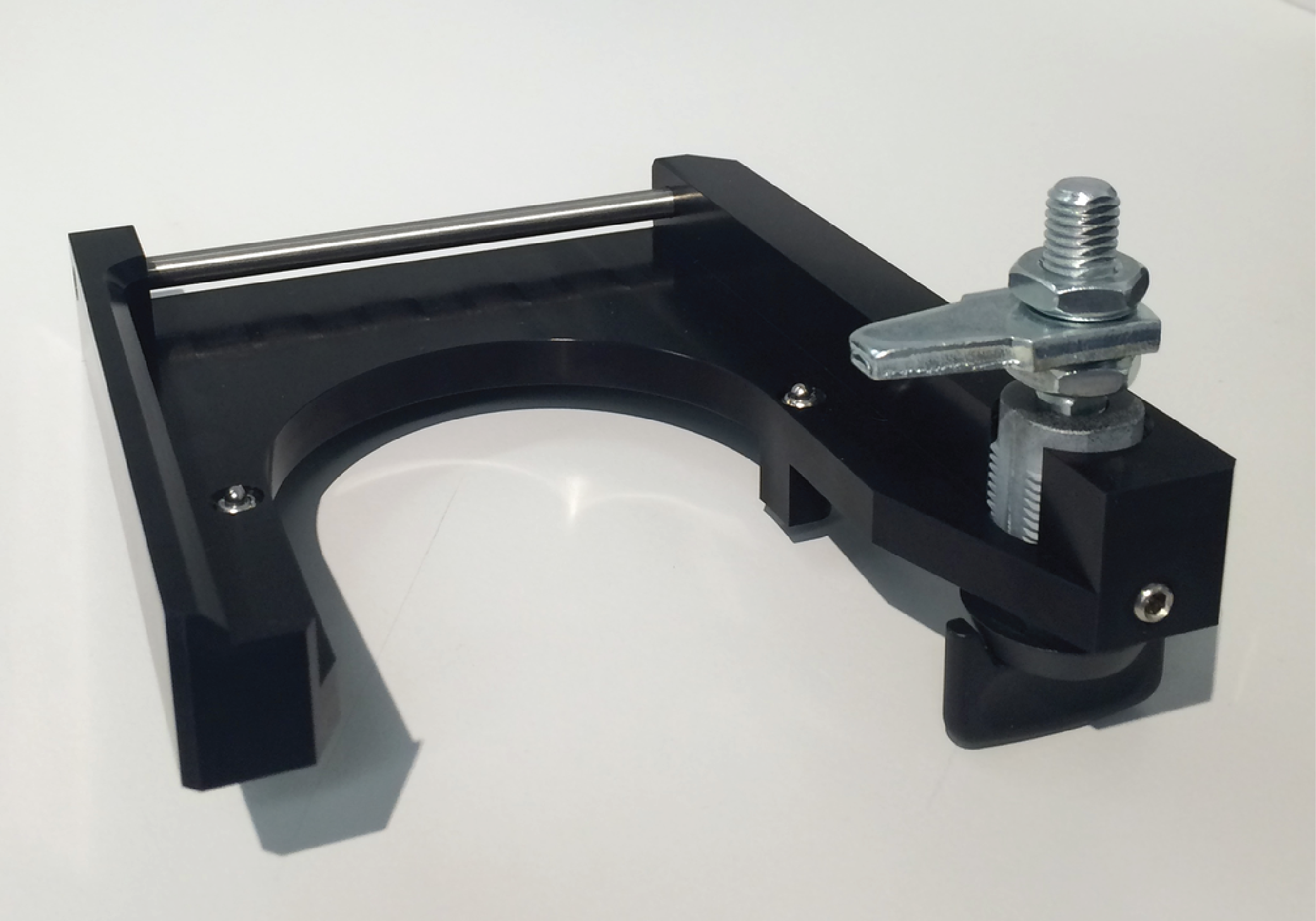
Fold mirror assembly: FoldMirrorAssemb
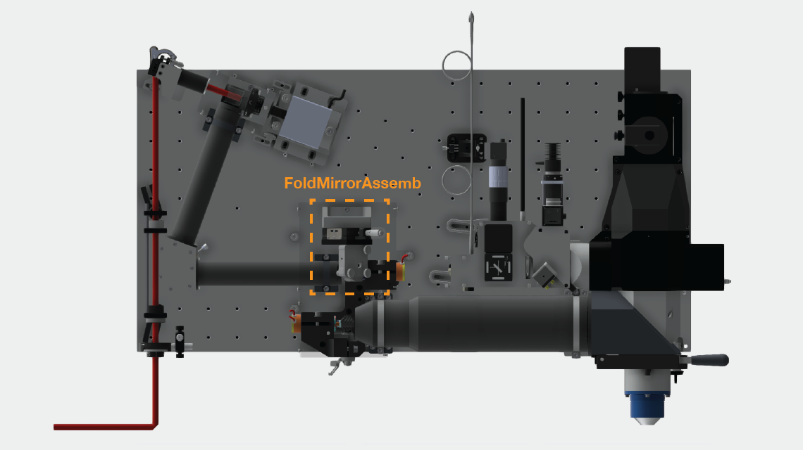

1) Attach translation stage to the FoldMirrAssembBracket.
2) Attach McMassterCarr standoff to FoldMirrAssembBracket
3) Attach gimbal mount to translation stage via adaptor plate.4) Adjust thickness of gimbal mount to 29.7 mm. The knob in the bottom corner should no longer be adjusted. Mark it with a red X to ensure it doesn't accidentally get changed during the setting of the compensators.
***INSERT PHOTO OF RED X on gimbal***
5) Cement the fold mirror centered to mirror blank (non-frosted side). Using norland 81. The mirror blank then fits inside the mount on the gimbal.
***Describe gluing procedure ***
***INSERT PHOTO OF FINISHED ASSEMBLY***
Imaging objective tray: IMOTrayAssby
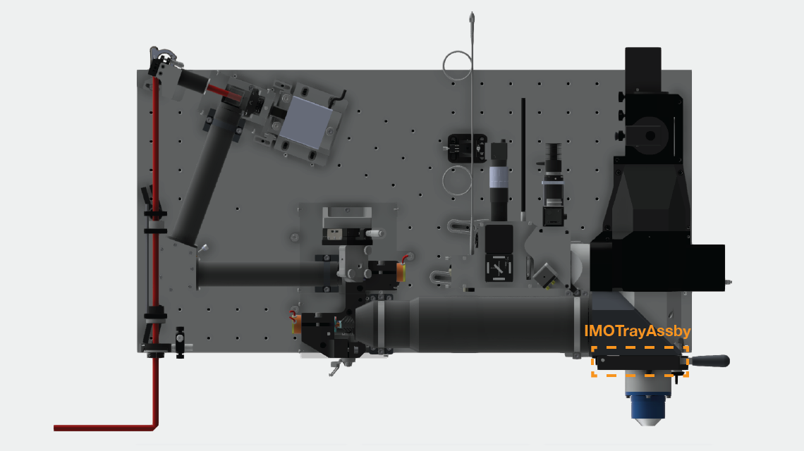
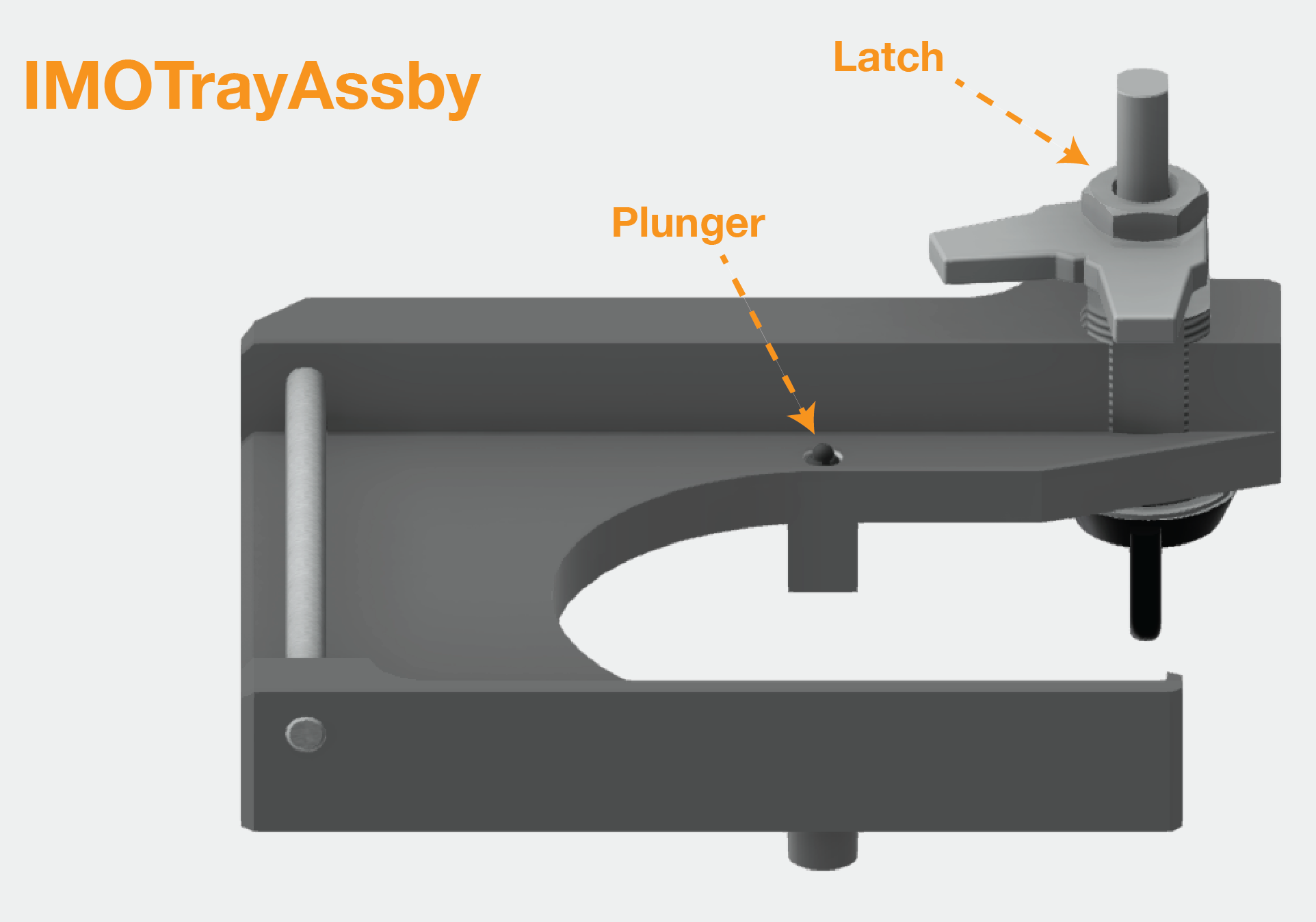
1) Set to of plunger to be flush with the metal surface of the tray
2) Slide dowel rod in place
3) Assemble latch, making sure orientation is correct when the latch is fully closed and open. The exact height of the latch will be set during final assembly.
Big detection lens and accessory optics dichroic holder: BigDetLensHolderAssby


DichroMotorBaseAssby

Assembling base plate, screw in bearings, make sure balls do not fall out of carridge
Glue magnets into base plate - make sure poles face in same direction **** INCLUDE PHOTO ***
Glue in rack with 5 min epoxy, push down hard so flush
MovingDichroAssby

Assembling slider & carriage
Motor assembly
Solder motor wires to carriage connector
Mounting of accessory dichoric / mirror (gluing to spider)
BigDetLensHolderOnlyAssby

Mounting slider in holder
Mounting lenses (big collection lens and accessory tube lenses)
MotorizedMirrorCoverAssby
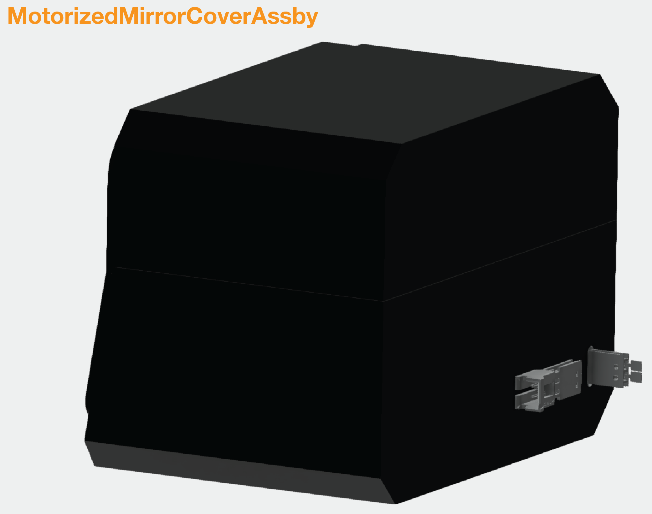
Assemble slider cover
Emission splitting dichroic assembly: EmissSplitDichroAssby

EntranceQtrWavePlateAssby
1) Position the post 4" post such that its top surface is 22 mm from the top surface of the RA90, and position the 1.5" post such that it is back surface 15 mm from the back surface of the RA90.
2) Attach the the rotation slider and the quarter waveplate.
Assembling compressor
Assemble the retroreflector carriage
1) Mount the AP90RL large angle bracket on the XT95P11 carriage.
2) Attach the TSX-1D stage to the AP90RL large angle bracket.
3) Use two M6 12mm screws to attach Thor_BA2F to retroreflector.
4) Attach the RS1:4 to the TSX-1D stage with a set screw.
5) Slide the BA2F onto the RS1:4. Adjust the orientation such that when the beam enters the retroreflector it will be reflected up without hitting an edge.
Assemble the 2x beam expander
1) Attach the SM1D12D ring iris to the GBE02-B 2x beam expander, making sure it is on the correct end.
2) Attach the SM1RC lens tube rings to the TR-05:4 posts and put them in the UPH3 universal post holders.
3) Slide the beam expander into the lens tube rings and tighten them
Assemble the prism pair compressor
Use norland 81 UV cure glue.
1) Glue prisms to TRT3 post with cutout. First glue the bottom prism, flush to the top surface of the post cutout, and positioned at a right angle. Put a few drops of UV cure glue on post and place prism on top. Do this inside a V-block to ensure the angles are correct. Once the bottom prism has been glued down, glue to top prism at a distance of 39.3mm (between outside faces). Then glue mirrors to prisms. Hold post in vice at correct orientation, place UV cure glue on prism and glue down mirror. Rotate post to glue second mirror.
2) Glue mirror and prism to polaris mirror mount, making sure orientation is correct. Attach this mirror mount to the top of the KB1X1 kinematic mount using a 8-32 screw and a nut.
3) Glue two mirrors and prisms to polaris mount and centering plate. First attach KCP2 centering plate to polaris mount. Glue one prism directly to the mount, then glue one prism to the the side of the centering plate. Leave a 1 mm space between the two prisms, and a 1 mm gap between the back face of the prism and the mount. Make sure the side of the prisms are both aligned to each other and the side of the polaris mount.
4) Attach the TRT3 post of the top plate of the KB1X1 kinematic mount using an AE8E25E internal to external thread adapter. The length of the external thread adapter needs to be shortened by about two threads to let it fit inside the TRT3 post.
5) Attach one polaris mount to the RM1F cube. Attach this cube with the RS2M spacer to the BA2 baseplate, making sure the cube is orientated such that the corner of the polaris mount is over the center of the BA2. Attach the BA2 to the Optosigma rotation stage, sliding the BA2 so the end of the slots is flush against the screws.
6) Secure the optosigma to the breadboard such that it is 25.3 mm from right side and 2.5 mm from top side.
7) Secure posts with polaris mounts to breadboard, matching the location of the items with their approximate locations in the breadboard. Ensure that the mirror, prisms all lie on the same axis.
8) Set the height of the KMCP to be 46.0 mm above the breadboard.
9) Glue custom prism onto polaris mount. Use norland 81. There are two polished and one un-polished side. Note prism is not an equilateral triangle. Make one side flush with polaris mount, and tip flush with other edge of mount.
10) Set the height of top of the iris holding posts to 87.0 mm
BeamPeriscopeAssby_2AxisStages_Solid
1) Glue a right angle mirror MRA20-P01 to polaris mount using norland 81, making side flush to bottom of mount and front flush to top of mount.
2) Glue a right angle mirror MRA20-P01 5.1 mm from edge with dial, and flush with the back of the stage.
3) Attach stages to the SolidPeriscopeBase, and attach the polaris mount to one of the stages in the correct orientation.
4) Remove redundant knob on polaris mount, as it should not be adjusted
Resonant mirror assembly: ResMirrChamber
1) Screw in schneeberger slider from underneath, make sure to use the correct 10 mm long screws so as not to damage stage
2) Add the stop screw, spring plunger, and threaded bushing (remove the lock screw) and lock nut, knob, and screw for positioning the stage.
3) Glue in the CRS resonant mirror cable using a black RTV sealant (Dow-Corning 732 multipurpose sealant), leaving 7" outside of the chamber. Let the glue cure overnight.
4) resonant mirror alignment in alignment rig - see photos below
UV cure a mirror to the resonant mirror alignment jig.
Slide the body of the resonant scanner inside its mount and then attach the mount to the alignment jig.
The alignment jig now has a mirror mounted on it – this is a reference point for the orientation of the resonant mirror.
An alignment laser should hit the resonant mirror and the alignment mirror at the same time.
Adjust the orientation of the resonant mirror carefully so that the two reflections overlap.
Height of the top edge of the resonant mirror should be 2.7 mm.


From left to right: Alignment jig with resonant mirror and alignment mirror; close-up of laser beam hitting the resonant mirror and alignment mirror; reflection from the two mirrors before alignment; reflections after alignment – they are on top of each other; height – resonant mirror center should be aligned with top edge of alignment jig (2.7 mm between edges).
5) At this point the resonant mirror can be mounted in the chamber. This is fairly tricky as it requires management of a fairly short cable.
Attach the cable to the mirror
Grab the resonant scanner mount with vice grip and inser into the chamber
The cable has to be trapped under the bottom of the mount - screw to the bottom of the chamber while pushing towards the alignment edge


From Left to right: Resonant mirror in its mount; holding the resonant mirror with vice grip; putting the resonant mirror into the chamber; trick to hold screws with hex key
Virtually conjugate galvo-galvo pair
Build alignment jig
Mount galvo mirrors on shafts
Setup alignment laser
Wire up and turn on galvos
Do alignment
XXXXX Prepare V-blocks — insert photo of parts with screws
IMOHolderAssemb
1) Add
Imaging objective mounting
Assemble imaging objective mount
Gluing kinematic mount
Assembling primary dichroic cap
Putting in spring plungers and set screws
Emission splitting dichroic assembly
PMT assembly
The goal is to couple the lens onto the PMT face with oil
Seal the edge of the PMT face to the PMT housing with 5 min epoxy - careful not to soil the plate above the photocathode
Add 30 - 50 ul of high viscosity oil
Place condensor lens on oil. Make sure there are no bubbles and carefully remove overflow oil from the housing.
Place a thin ring of quick seal (WPI) on the PMT housing around the lens
Assemble alignment jigs
Alignment jig cage assembly
Imaging objective alignment jig mount
Remote focus objective assembly
The polarizing beam splitter (pbs) needs to be glued to the remote focus objective mount
The PBS needs to have the three sides marked by arrows facing the beam.
The beam needs to be flush with the alignment edges on the mount
The UV transmission of the cube is low, so be sure to expose the glue to UV for ~ 2 minutes or so
Mount the quarter wave plate as shown in the model.
Mount the remote focus objective (using 2.5 mm captive screws - Mouser 761-m0277-ss)


Left, remote focus objective mount, quarter waveplate holder, quarter waveplate, and polarizing beamsplitter. Right, components mounted on remote focus mount, including remote focus objective.
Mounting the large relays 1, 2, and 3
Relays 1 & 2 require 1.5" 1/4 20 socket screws
Relays 3 requires 2.5" 1/4 20 socket screws
Mount as shown in the photos


Left, mounts for relays 1 & 2. Right, relay 3
Assembling the covers
Assembling objetive mounted optic holder
Accessory optics
1) Remove galvo mirrors from mount
Mounting galvo driver and resonant driver boards (Spencer / Steve documentation)
Making samples
Beads
Fluorescein
Accessory optics
SECTION 2: MOUNT ON BREADBOARD
Mounting on the breadboard
Put dowel pins into holes
Mount brackets for PupilRealy3 first, make them pressed against the pins and their angled side facing down
Mount pupil relay 3, push so all the way to the left (edge against mounting surface). Tighten down clamps with screws with springs. Make sure nuts are in right place.
Mount IMOholder and tray, pushed it against the table and pins.
Mount primary dichroic, make sure caret faces down
Add primary dichro cap, pressing it against vertically mounted breadboard
Add bigDetLensHolderAssby - note need a 1/2 inch 10-24 screw to secure top right part
Add detLensCap
Mount the galvo block, pushing it against pins. Note there is not a lot of space between the galvo mirrors and pupil relay 3
Attached pupil relay 2 to the resonant chamber
Use long handle quarter-20 hex drive to mount resonant chamber to breadboard. Use paper trick to get screw sitting on ball end of hex drive, and then screw chamber down.
Attach pupil relay 1 mount to breadboard
Attach pupil relay 1
Attach remote focus objective assembly
SECTION 3: WIRING
Set up scanimage
Machine data file setting
Wiring galvos / voice coil / PMTs / etc.
SECTION 4: TABLE OPTICS ALIGNMENT
Align table optics at 900nm with the laser in alignment mode
1) Mount pockels cell just after laser, and align so that beam goes through it. Then manually set pockels cell power to about 10% for the rest of the alignment procedure.
2) Place beam expander after pockels cell. Adjust its height and the position of the front entrance such that the beam passes through the center of the iris on the beam expander. Adjust the position of the back end of the beam expander such that the beam passes straight through it. Adjust the beam expander so that the beam is collimated.
3) Position two silver mirrors such that the beam hits their centers and is steered towards the PPC. Make sure the beam remains level at its original height. Do this using an IR card stuck to a support to check beam height at different positions.
4) Place the uniblitz shutter just before the PPC in the path of the beam.
5) Adjust the positions of the enterance and exit irises at the beginning and end of the PPC so that the beam passes centeres through them.
6) Adjust height and lateral position of first two mirrors such that the beam hits both of them in the center. Then adjust the orientation of the mirrors so that the exiting beam direction is normal to entrance beam.
7) Position the large silver mirror such that the beam is centered on it, and adjust the mirror position such that the reflected beam is parallel to table and then adjust its angle it is entering prism close to its far edge.
8) Now adjust angle of prism to find the angle of minimum deviation using rotation stage (coarse). Do this by placing an IR card far away and rotating prism to find angle where beam is furthers to the right.
9) Now make sure reflected beam and incident beam are coplanar by adjusting the angle of the prism and looking at the height of the reflected beam on the IR card. The reflection is very faint and needs an IR viewer to be seen.
10) Now make sure the refracted beam is coplanar with the reflected and incident beam by adjusting the other angle of the prism.
11) Redo finding angle of minimum deviation using fine adjustment. This will be the angle where the beam is the rightmost possible.
12) Algin retroreflector axis. Adjust height of retreflector such that the return beam is centered on the roof mirror. Then adjust close side of rail such that the returning beam is hitting the prism a little further into the prism (2 to 3 mm). Then adjust the back position such the rail is exactly parallel to the beam. Slide the retroreflector back and forth along the rail to check that it is moving along the axis of the beam.
13) Adjust lateral position of roof prisms so that return beam is entering the prism, and rotate it so that the outbound beam 3 is hitting the retroreflector. Do fine angle adjustments of the prisms angle such that return beam 4 is level to table and colinear with track.
14) Mount output coupler. Place in bypass mode, and set target card after exit iris. Left bypass mode. Align exit beam to pass through iris and hit target by adjusting height of retroreflector so that beam passes through center of exit iris and move mirror to translate mirror, and use angle of mirror to make beam hit target on iris card.
15) Add two mirrors such that beam is level as it goes into the entrance of periscope.
16) Set periscope entrance mirror center to be 120 mm heigh (height of laser beam).
Pockels cell
Shutter
2x table beam expander
Assembling the compressor
Build enclosure for table optics
SECTION 5: MICROSCOPE ALIGNMENT
Multistage periscope alignment
Quarter wave plate adjustment for multistage periscope
Alignment of beam to remote focus objective
Adjustment of quarter wave plates for maximum transmission
Alignment of RF mirror assembly
Alignment of beam to imaging objective using compensators
Adjustment of galvo voltage divider gain
SECTION 6: IMAGING
Dye pool imaging to set compensators
Dye pool imaging to set retroreflector position
Image beads and measure PSF
APPENDIX A:
Accessory optical path
Assembly, alignment, calibration, adjustment