Assembling compressor
Assemble the retroreflector carriage
1) Mount the AP90RL large angle bracket on the XT95P11 carriage.
2) Attach the TSX-1D stage to the AP90RL large angle bracket.
3) Use two M6 12mm screws to attach Thor_BA2F to retroreflector.
4) Attach the RS1:4 to the TSX-1D stage with a set screw.
5) Slide the BA2F onto the RS1:4. Adjust the orientation such that when the beam enters the retroreflector it will be reflected up without hitting an edge.
Assemble the 2x beam expander
1) Attach the SM1D12D ring iris to the GBE02-B 2x beam expander, making sure it is on the correct end.
2) Attach the SM1RC lens tube rings to the TR-05:4 posts and put them in the UPH3 universal post holders.
3) Slide the beam expander into the lens tube rings and tighten them
Assembling the prism pair compressor
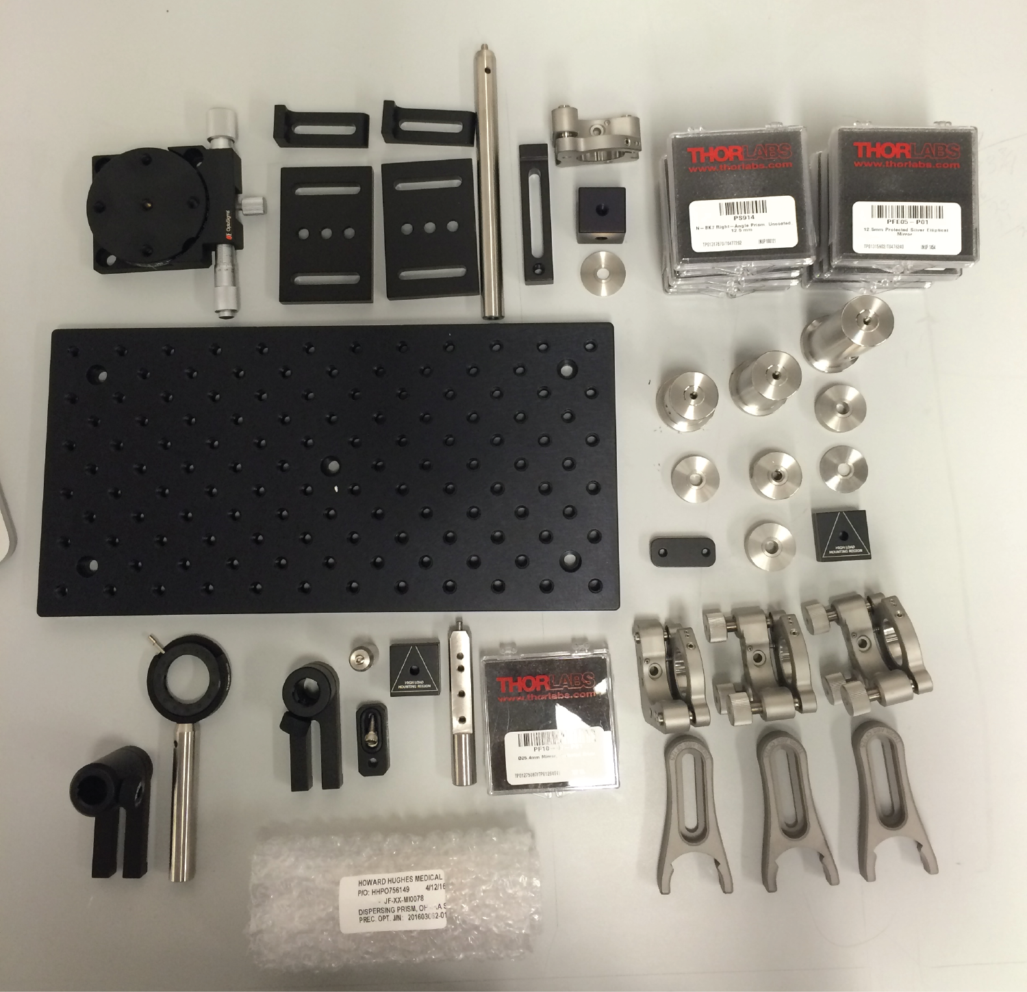
1) Glue prisms to TRT3 post with cutout using norland 81 UV cure glue. First glue the bottom prism, flush to the top surface of the post cutout, and positioned at a right angle. Put a few drops of UV cure glue on post and place prism on top. Do this inside a V-block to ensure the angles are correct. Once the bottom prism has been glued down, glue to top prism at a distance of 39.3mm (between outside faces). Then glue mirrors to prisms. Hold post in vice at correct orientation, place UV cure glue on prism and glue down mirror. Rotate post to glue second mirror.
2) Glue mirror and prism to polaris mirror mount, making sure orientation is correct. Attach this mirror mount to the top of the KB1X1 kinematic mount using a 8-32 screw and a nut.
3) Glue two mirrors and prisms to polaris mount and centering plate. First attach KCP2 centering plate to polaris mount. Glue one prism directly to the mount, then glue one prism to the the side of the centering plate. Leave a 1 mm space between the two prisms, and a 1 mm gap between the back face of the prism and the mount. Make sure the side of the prisms are both aligned to each other and the side of the polaris mount.
4) Attach the TRT3 post of the top plate of the KB1X1 kinematic mount using an AE8E25E internal to external thread adapter. The length of the external thread adapter needs to be shortened by about two threads to let it fit inside the TRT3 post.
5) Attach one polaris mount to the RM1F cube. Attach this cube with the RS2M spacer to the BA2 baseplate, making sure the cube is orientated such that the corner of the polaris mount is over the center of the BA2. Attach the BA2 to the Optosigma rotation stage, sliding the BA2 so the end of the slots is flush against the screws.
6) Secure the optosigma to the breadboard such that it is 25.3 mm from right side and 2.5 mm from top side.
7) Secure posts with polaris mounts to breadboard, matching the location of the items with their approximate locations in the breadboard. Ensure that the mirror, prisms all lie on the same axis.
8) Set the height of the KMCP to be 46.0 mm above the breadboard.
9) Glue custom prism onto polaris mount. Use norland 81. There are two polished and one un-polished side. Note prism is not an equilateral triangle. Make one side flush with polaris mount, and tip flush with other edge of mount.
10) Set the height of top of the iris holding posts to 87.0 mm