- Set laser to central wavelength, 970 nm
- Manually adjust pockels to about so beam is just bright enough on card to see
- Check beam is still passing through irises of PPC in bypass mode
- Adjust angle of prism such that beam passes through center of exit iris
- Direct beam into bottom of table periscope, through an iris on the table and the iris on the bottom of the periscope
- Add the quarter waveplate before the gantry periscope on the table, Set it 45° to the fast axis to make the polarization circular going into the gantry periscope.
The gantry system translates the microscope along 3 axes (X,Y,Z) and rotation (θ). Ideally, the beam should not deviate during movement of any of the four translations. Any movement results in a deviation of the beam onto the back aperture objective and consequently affects the scanned image. Therefore, a multi-mirror periscope which consists of 6 mirrors (See picture below) was engineered in order to allow sufficient control of the beam alignment onto the vertical breadboard. Completion of this alignment defines the beam propagation on the vertical breadboard to which all vertical breadboard optics should be aligned to.
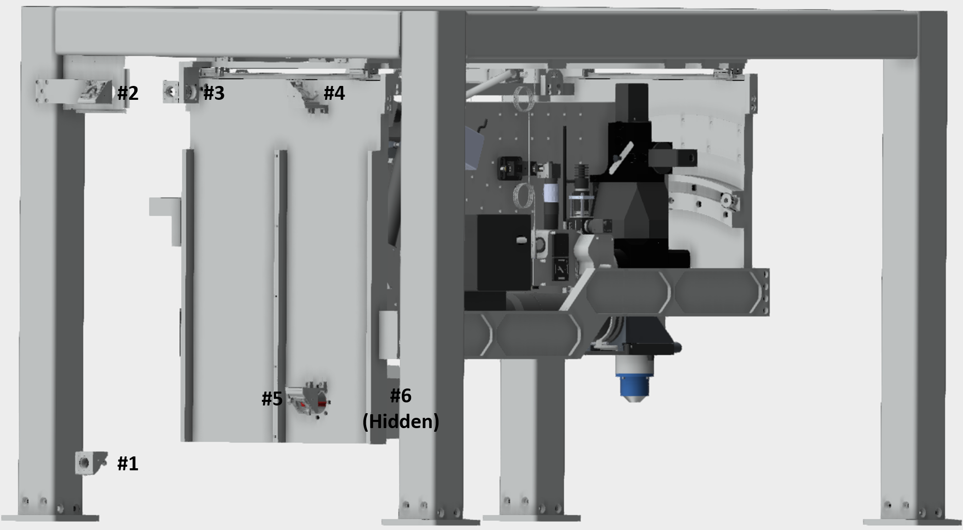
Coarse alignment of gantry periscope: The first step is a coarse alignment, this just ensures that the beam is roughly going through the center of each of the six periscope mirrors. This safeguards that the beam won’t clip on the housing when fine adjustment commences.
-Adjust the last two mirror from the prism compressor such that the beam is parallel to the plane of the table and hits periscope mirror #1 at 45° directing the beam up to periscope mirror #2.
-Adjust the knobs on periscope mirror #1 such that the beam is roughly centered on periscope mirror #2
-Adjust the knobs on periscope mirror #2 such that the beam is roughly centered on periscope mirror #3
-Adjust the knobs on periscope mirror #3 such that the beam is roughly centered on periscope mirror #4
-Adjust the knobs on periscope mirror #4 such that the beam is roughly centered on periscope mirror #5
-Adjust the knobs on periscope mirror #5 such that the beam is roughly centered on periscope mirror #6
It is essential that the beam does not deviate when any of the four translations of the gantry are moved. In order to confirm this property each axis must be tested and aligned individually. While one could monitor the deviation coarsely by eye for fine alignment a digital readout is essential. Therefore, it is best to use a camera, beam profiler or position sensitive detector to monitor beam deviations.
Place the sensor far away from the periscope. Ideally, this sensor is placed after the remote focus and objective jig. **At this point the telescope, remote focus objective and voice coil should be removed. Use the vertical breadboard periscope to roughly center the beam through both irises from the jig onto the center of the detector. This large separation ensures any small beam deviation will result in a detectable change in the position on the sensor. First, start the gantry to one extreme of its travel and note the location of the beam on the sensor. Next, move the gantry to the other extreme and record its position on the sensor. If the input beam is perfectly aligned to the axis of travel the two positions should not change. In practice some difference will always be observed albeit small since the alignment is limited by the linearity of travel along the axis.
A particular axis alignment is controlled by a specific periscope mirror for linear axes X, Y and Z and 2 periscope mirrors for rotation. These relationships were defined by how the mirror mounts are attached to the gantry. Consequently, there is a particular order and a specific beam alignment to how the periscope is aligned to the mounted breadboard. The order is as followed;
-Periscope mirror #2 for Y axis.
-Periscope mirror #3 for X axis.
-Periscope mirror #4 and #5 for rotation.
-Periscope mirror #6 for Z axis.
- Move gantry system back and forth in y. Adjust top mirror on periscope gantry such that the beam remains stationary on the camera.
- Move gantry system back and forth in x. Adjust first mirror inside box (high up) such that the beam remains stationary on the camera.
- For rotation need to control four degrees of freedom, so have to move camera between two locations on the vertical breadboard (near) and (far, where it is now). The second location is ideally where quarter waveplate goes (near camera). Have to keep beam centered on both. First keep centered on near camera using far mirror, the one that comes next after one used for x, (high up and closer to vertical breadboard). Then keep centered on far one using mirror at bottom of gantry to keep centered on far one. Watch beam move on camera during move, use mirrors to adjust beam position to be at the center of the curvature of the circle traced out by the beam. THIS CAN BE QUITE TIME CONSUMING - IN PART BECAUSE THE GANTRY ANGLE HAS TO BE MOVES BACK AND FORTH.
- Aligned z axis using mirror inside the rotation bearing, keeping beam constant on the camera in the far position.
- All alignments for each axis is iterative. Therefore, it might take multiple iterations before acceptable alignment is achieved. Successful alignment requires patience.
- Add in the other quarter waveplate, set to minimum reflection (maximum transmission) through polarzing beam splitter. Put the card to look at the reflected beam and make it as dim as possible.
- At this point, if the the first quarter waveplate (QWP #1), outside of the microscope cage, is not rotated ideally, then there will be some change in transmitted intensity through the PBS as the microscope rotation is changed. To fine tune the angle of QWP #1, use a power meter to check the beam power after the PBS (remote focus objective is removed) while rotating the microscope back and forth. Observe the power difference, and make small adjustments to the rotation of QWP #1 (rotating QWP #2 each time afterwards to maximize transmission) until the power difference upon microscope rotation is minimized.
- Add in the beam expander. There is an iris on the front. Position so that beam goes through it with the whole assembly centered.
- Add the beam alignment jig (two 60mm cage plates with irises and long cage rods) to the remote focus objective location, using the RFAlignmentJigInterface (part J003123).
- Move the entire beam periscope assembly such that the beam is centered on two periscope mirrors. Align output beam through the two irises on the remote focus alignment jig using the two translation stages on each periscope mirror (which should produce pure translation), and the two tilt knobs on the Polaris mount in the periscope. The beam should be centered on the first iris, and the angle of the beam should coincide with the jig axis (shadow of first iris in beam overlaps with second iris). It helps to use a beam camera to view the centration of the beam on the first iris in the alignment jig (set using the two mirror translations).
- Mounting the voicecoil. (The remote focus objective and RFAlignmentJigInterface should be off.) The dowel pins are used to guide the voice coil assembly during mounting, but the exact position of the assembly is set using the nudgers. The lateral position of the beam is adjusted by changing the angle of the voice coil assembly with the two nudgers. Do this while looking at the back reflection on a card near the entrance to the large bearing. The yaw position of the beam is then adjusted by tipping the voice coil assembly. This procedure ensures the mirror is perpendicular to the beam. Look at the beam back near where the quarter waveplate. If you ever see a beam on the card then you know you aren't aligned.
- Once the voice coil mirror is aligned remove the voice coil and add remote focus objective back on.
- Remount the voicecoil on the vertical breadboard. First, loosen the z-adjust of the voicecoil (screws which go through stock Thorlabs baseplate), and move voicecoil AWAY from where the remote focus objective will be, so that there is not a crash when the voicecoil is mounted. Add the voicecoil back onto the rig, being sure to touch nudgers to set angle properly.
- Now the proper z-position of the remote focus mirror will be set. Turn voicecoil on (read manual and use Hyperterminal, make sure it is enabled (k1 or k3 command) and voicecoil is stiff) and set control voltage to approximately 4V (this is to bias the usage range such that the remote focus mirror is less likely to crash into the remote focus objective if something unusual occurs–note that the LFA2004 that is being ordered specifically for the 2p-RAM has an analog command range of +/-10 V, mapping to +/-2 mm, not the +/- 2.5V range that is mentioned in the manual). The mirror will be slowly advanced towards the remote focus objective (physically, not using control voltage), until the beam exiting the remote focus objective is roughly collimated. If the new, in situ procedure for aligning the resonant mirror is being followed, and PupilRelay1 and PupilRelay2 are not present, then the beam can be seen directly after it reflects off of the polarizing beamsplitter cube. If PupilRelay1 and PupilRelay2 are present, then the beam can be observed in the space between the two y-axis galvo mirrors, where the beam is traveling downward. In this space, the remote focus mirror is in the approximately correct location when the beam size here is 11mm in diameter. At any time, the quarter wave-plate that is closest to the remote focus objective can be adjusted to maximize the beam power traveling through the rest of the microscope
- If the in situ procedure for aligning the resonant mirror is being followed, then it should occur now. Afterwards, add pupil relays 1 and 2 back, following procedure here.
- At this point, mount the MainAlignmentJigInterfaceAssby to the main imaging objective space. This will send the beam out horizontally and the beam should be visible using an IR viewer. Collimate the beam by adjusting the voicecoil control voltage (in ScanImage, the linear scanner offset voltage will be used) until the beam size stays roughly constant while propagating a few meters.
- Add the alignment jig (two 60mm cage plates with irises and long cage rods) to the MainAlignmentJigInterfaceAssby to observe the beam alignment at the imaging objective space. The 3 galvo mirrors should be engaged, set to the 0 position (use Point function in ScanImage), and should have been previously aligned relative to the galvo mounting block. Use the 4 compensator knobs (the resonant mirror translation, and the translation and tilt in two dimensions of the fold mirror that proceeds the galvo mirror assembly) to align the beam to the alignment jig, similarly to how the beam was aligned to the alignment jig when it was in the remote focusing objective space using the 4 knobs on the small beam periscope.
- At this point the beam should be roughly aligned simultaneously to the remote focus objective and imaging objective. However, to achieve good remote focusing performance, the image of the pupil of the remote focusing objective and pupil of the imaging objective need to be aligned (translation-wise) precisely. This requires adjustment of the 4 compensation knobs while looking at imaging performance in real-time. Use the following procedure:
- Remove the MainAlignmentJigInterfaceAssby and mount the imaging objective.
- Prepare slide with large, deep well of fluorescein dye and proper coverglass thickness. This slide needs to be mounted relative to the imaging objective at the right distance, and orthogonal to the optical axis. There are two ways to do this:
- Using AccessoryHolder_Simple (part J005700A). Attach this to the objective, and attach dye pool slide to it, as shown in AccessoryHolder_Simple_Assby.dwfx.
- Taking advantage of the known beam collimation and alignment entering the imaging objective. See video attached below. The slide is mounted to the optical table and approached by the imaging objective, with field curvature correction turned off in ScanImage. Use a full FOV, striped MROI setup in ScanImage such as roiTile10umPixels.roi. With the beam collimated at the imaging objective, the microscope should be lowered until the focus is 355um below the top of the dye pool. This is the natural focus position, as designed, and all imaging of slides or animals should occur at this coverglass-objective separation (+/- 100um, see below) for ideal imaging. Then, the remote focus (fast Z in SI) should be adjusted until the focus is just below the top of the dye pool (depth/V scaling in SI MDF should be adjusted so that the proper values, in um of depth, can be used in SI). A spot smaller than the FOV should be seen in the image, which has an outline that is the intersection of the curved imaging plane with the top of the dye pool. This spot will move in the imaged FOV as the objective-slide relative angle is changed, and should be centered when the optic axis and slide are orthogonal, as long as the beam is aligned to the optic axis at the center of the scan field (previous alignment step). Adjust the objective-slide angle (one axis is accomplished through microscope rotation, and the other can be adjusted by putting the slide on a goniometer or other tilt stage) until the imaged spot is centered.
 Alignmenttomicroscopeusingdyepoolimage-1.m4v
- At Janelia, it was found that the two methods above did not agree very well. That is, when the beam was adjusted to be collimated and angularly aligned at the objective, and when using the AccessoryHolder_Simple, the focus was not found to be 355um below the top of the dye pool (there was a ~200um difference from what was expected here), and the spot showing the intersection of the imaging sphere and dye pool top was not centered in the imaged FOV. It's not known what caused these discrepancies, but some amount of compensator adjustment was carried out using both methods of initial alignment, and it seemed that similar final performance should be achievable in either case. It may be a good idea to check both alignment methods, but as long as the discrepancies between them are less than ~250um in distance, and 1 deg in angle, similar final performance can probably be achieved, and it is probably best to use the alignment method that is most like what will be used when doing daily experiments. I.e. if the animal is attached to the optical table, the latter method can be used to align the objective and animal, and should be used to do the compensator adjustment; if the animal is attached to the objective somehow with a position and accuracy similar to that designed into AccessoryHolder_Simple, then the former method should be used.
- A THIRD method for aligning the slide angle is using the Coverglass Alignment module in the accessory optical system. See attached video below. This system can be calibrated using the AccessoryHolder_Simple part, most easily by mounting a piece of glass such as an OD 4 ND filter on it (this will show a reflection that is imaged onto the coverglass alignment camera only from the top surface). With this alignment step, using this system should give an alignment equivalent to mounting the slide onto the AccessoryHolder_Simple part, and using this system should allow a greater alignment sensitivity than the method of observing the intersection of the image sphere with the coverglass bottom. That being said, this extra sensitivity may not lead to much increase in signal level, as the objective-coverglass alignment was not found to very sensitively affect the signal level.Coverglassalignmentsystem-1.m4v
- Turn on field curvature correction in SI (see adjustment video below), adjust Fast Z (remote focusing) until focus is a little below the top of the dye pool, such that it's easy to see how well the field curvature correction is working. Adjust the field curvature correction radius of curvature (in MDF) and Fast Z Lag Time (in SI Fast Z dialog box) until field curvature correction works as well as possible.Fieldcurvaturecorrectionadjustment-1.m4v
- With slide and objective properly aligned, begin MROI imaging with field curvature correction on. Set up ~15 small (500 x 500 um) ROIs around the entire volume FOV. At Janelia we use 5 ROIs–top, bottom, left, right, center–in three planes. As to the precise location of the ROIs, they should be close to the edges of the used FOV, so that performance at these locations is optimized, but not TOO far out. Edges at 2.4mm from the center, and planes at 100um below the top (make sure no ROIs image above the top of the dye pool), 300 um, and 600 um should work fine. See example roi group roigroupOptimize_NotFullResWidth_ToEdges_100-500-1000.roi (these perhaps go too deep–we were checking limits of remote focusing performance). Make sure there are no bubbles, artifacts, or dye pool walls near any of the ROIs, as these may wander into the ROIs during optimization. Image all ROIs in MROI mode, and with a few frames rolling average to reduce noise, then adjust compensator knobs (putting arm through small door in side of cage while room is darkened) to maximize the average signal over all ROIs. The SI user function userFunctionBar.m can be used to display the integrated signal across each ROI in real-time (first n bars, where n is the number of ROIs), plus the average signal over all ROIs (n+1 bar). At first, use the bars function with norm=0 (parameter in userFuntionBar.m file) to simultaneously roughly maximize the signal across all ROIs and make sure that the signal is not highly non-uniform across the ROIs. It will probably be impossible to make the signal highly uniform across the ROIs, and there may be some trade-off between uniformity and maximum total average signal. To fine tune, switch to norm=1 to see the signal relative to the last acquisition made. See video below. Here is the basic compensator adjustment strategy:
- There are two sets of adjusters which works more-or-less orthogonally to each other–the translation and tilt along one axis, and the translation and tilt along the other axis. Look at the fold mirror mount to figure out which tilt goes along with which translation axis. ALL 4 knobs can misalign the remote focus objective and imaging objective pupils, so the signal intensity of the ROIs will depend on each of them sensitively. However, it will be found that for each pair of adjusters there is a global maximum that can be found by tweaking one knob, remaximizing with the other, and then looking at how the signal level changes as this is repeated. In effect, this is adjusting the center of the scan range for this axis while keeping the pupils aligned, and this has a much smaller signal sensitivity than the pupil alignment itself. Iterate back and forth a few times between optimizing with two adjusters, and then the other two.Compensatoradjustmentsetup-2.m4v
- There are two sets of adjusters which works more-or-less orthogonally to each other–the translation and tilt along one axis, and the translation and tilt along the other axis. Look at the fold mirror mount to figure out which tilt goes along with which translation axis. ALL 4 knobs can misalign the remote focus objective and imaging objective pupils, so the signal intensity of the ROIs will depend on each of them sensitively. However, it will be found that for each pair of adjusters there is a global maximum that can be found by tweaking one knob, remaximizing with the other, and then looking at how the signal level changes as this is repeated. In effect, this is adjusting the center of the scan range for this axis while keeping the pupils aligned, and this has a much smaller signal sensitivity than the pupil alignment itself. Iterate back and forth a few times between optimizing with two adjusters, and then the other two.
- At any point in the MROI signal optimization imaging, the position of the retroreflector in the prism pair compressor can be optimized. This should be done. Due to the properties of the retroreflector, it can be freely moved without adjusting the beam alignment downstream of the PPC. Unless this was already set very close to the optimum location (optimum GDD), a large gain in signal level should be seen.
- After optimizing the signal using the 4 compensator knobs, try adjusting the galvo Y1 gain adjustment, which should in effect adjust the location off the Y galvo scan pupil location. If the signal can be improved with this adjustment, then iterate back to the 4 alignment compensator knobs again.
- Finally, see if the signal can be improved through adjusting the beam alignment entering the microscope using the 4 knobs on the small beam periscope. Ideally, the sensitivity should be low here, and the knobs should be at or near their optimum positions, since moving these should misalign the beam going into the remote focus objective. If a large improvement in signal can be made, then perhaps the beam got misaligned before starting the entire procedure.
- NOTE! After adjusting the compensator knobs, the center of the scan range will probably no longer be aligned as well to the optical axis of the imaging objective. With the field curvature correction off and the focus slightly below the surface of the dye pool, look at where the image sphere/dye pool top intersection spot is located in the FOV. If the location of this spot is used in the future to align the objective-coverglass angle for imaging, then the current position (NOT center position) should be used as the goal.
- The alignment should now be complete, and PSFs can be measured using, for example, beads mounted in agar.
- Over a period of weeks, the beam entering the microscope may be found to wander slightly, probably due to alignment drift coming out of the laser. This should be monitored at the entrance pupil of the beam expander on the raised microscope baseplate, for example by looking at the shadow of the pupil relative to the beam using a NIR beam card where the beam enters the remote focus assembly. The fix this alignment, multi-stage periscope mirror #1 (see image above) should be used.
Overview
Content Tools
31 Comments
Daniel Flickinger
For workshop attendees: During the workshop, I may have advocated for using the AccessoryHolder_Simple_Assby (the piece that mounts onto the imaging objective, and can hold a slide) to collimate the beam at the imaging objective, by looking at when the focus first enters the dye pool of an appropriately constructed/mounted dye pool sample. In my later experience, this didn't work as well as I had hoped (I found at least a couple hundred micron depth discrepancy, compared with collimating the beam accurately using a wavefront sensor). It's probably best to collimate by looking at the beam, as stated above. That being said, there is probably not a large difference in microscope performance when looking at a constant depth in a sample, and while simultaneously focusing the whole microscope +/- ~200um and adjusting the remote focusing to compensate.
Rob Campbell
Any tips on what to do if the beam is clipping the housing of mirror #4 when adjusting mirror #3 for the X axis? I perfomed the initial centering and adjusted #2 for the Y axis before doing mirror #3.
Natalia Orlova
Rob, I had the same clipping problem and re-aligned with a compensating offset on mirror 1 to add pure translation of the beam when traveling along X axis. In the result, the beam entering mirror 1 was not exactly centered (slightly "lower"), which propagated to mirror 2, and 3, and was finally centered on mirror 4.
Rob Campbell
I tried this and managed to get the beam stationary on the beam profiler with it mounted on mirror #5 but when I place the profiler where the QWP is then I see 300 microns of drift that I can't correct without the beam again clipping on #4. At the suggestion of Brian from ThorLabs I decided to move on to the rotation alignment and go back to the X motion once that's done. On my rig X motion seems to cause a small amount of rotation that shows up on the encoder.
Unknown User (bmehl@thorlabs.com)
That seems to be the right idea. An inability to move #3 without it clipping on #4 suggests that mirrors #1 & #2 need to be adjusted such that when the y-axis travels the beam is centered on the input of #3 and the beam does not move during y-axis travel. The best way to tell is with a position sensitive detector or camera. Additionally, you may need to adjust #3 fine adjustment screw (the one without a knob) for mirror surface translation. This guarantees that a beam coming in centered on the aperture is able to leave the output aperture centered and perpendicular to the output aperture plane. Where is the beam clipping on #4?
Rob Campbell
Hmmm... The beam enters near the lower edge of mirror four's entrance aperture and clips coming out, so I can look into the translation knob for that, but possibly the problem is up-stream so I'll double check the path from #1 to #3.
Rob Campbell
Brian, if understand correctly are you saying that the procedure is:
a) Adjust #2 to eliminate Y drift (whilst adjusting #3 to ensure the beam stays on the profiler).
b) When (a) is done, check whether the beam is centered on the entrance aperture of #3.
c) If not, centre the beam it using #1.
d) Repeat until the beam is centred on #3 and there is no Y drift.
Then move on to adjusting the X drift.
Unknown User (bmehl@thorlabs.com)
a) Adjust #2 to eliminate Y drift (whilst adjusting #3 to ensure the beam stays on the profiler).
If the y-axis is aligned properly you should not need to adjust #3 as the beam will not move on the profiler during y-axis translation. You will only move #3 to align the x-axis.
b) When (a) is done, check whether the beam is centered on the entrance aperture of #3.
Yes, when the y-axis is aligned properly the beam is centered on the entrance aperture of #3
c) If not, centre the beam it using #1.
Yes, you will need to use the pair #1 and #2 to make sure that it is centered and the beam doesn't drift on the profiler during y-axis translation.
d) Repeat until the beam is centred on #3 and there is no Y drift.
Yes, once it is centered you can use mirror #3 horizontal and vertical knobs to sent it to the center of mirror #4. Slight tuning of the #3 fine adjustment screw may be required to achieve both centering beam on #4 along with beam not moving on the profiler during x-translation.
Hope this helps.
Rob Campbell
If the y-axis is aligned properly you should not need to adjust #3 as the beam will not move on the profiler during y-axis translation. You will only move #3 to align the x-axis.
Ok, but during the alignment process of Y, the beam will translate across the beam profiler and needs re-recentering. You're saying that this re-cenerting shouldn't be done using any of the periscope optics?
The rest is clear. I'll give it another go tomorrow. Thanks!
Unknown User (bmehl@thorlabs.com)
Yes, in that case it's fine. If it needs re-centering than the coarse alignment is not very good. You should be able to coarse align the periscope by eye first. For example (y-axis), you can set a target indicating the center of #3 entrance aperture (Iris & IR viewer, IR fluorescing alignment disk, etc) and look for translation as you move the gantry along y-axis. After, adjust mirror pair #1 & #2 such that no movement is seen on the target. For fine alignment, set up the profiler. This way the beam shouldn't walk off the profiler during adjustment. Either way should achieve the same result, it's really just personal preference.
Anonymous
Step 23: "...and set control voltage to approximately 4V ..." : I see that the control voltage should be between -2.5V and +2.5V. Instead, did you mean the voltage you read on the voice coil controller test point TP2, which will be between (-4 and +4V)?
Also could you provide your voice coil configuration parameters (obtained by typing d1 in a hyperterminal window) ? It seems the voice coil factory configuration needs modifications (e.g. I had to modify the motor position fault conditions such that it does not fault right away).
Thanks!
Stephan Thiberge
Step 23: "...and set control voltage to approximately 4V ..." : I see that the control voltage should be between -2.5V and +2.5V. Instead, did you mean the voltage you read on the voice coil controller test point TP2, which will be between (-4 and +4V)?
Also could you provide your voice coil configuration parameters (obtained by typing d1 in a hyperterminal window) ? It seems the voice coil factory configuration needs modifications (e.g. I had to modify the motor position fault conditions such that it does not fault right away).
Thanks!
Daniel Flickinger
I think that I did mean the control voltage should be 4V. Where did you see that it should be between -2.5V and 2.5V? I could be remembering wrong.
We should post an updated machine data file (this would have the ~4V setting in it) and the voice coil config parameters, but I'm out on vacation this week. I'll see if Nick or someone can get those for you.
Stephan Thiberge
Hi Dan,
The -2.5V and 2.5V limits are coming from the online manual of the voice coil controller.
Also for now, I don't know what I am doing wrong, but I can't get the analog control of the voice coil working. I spent a few hours on it, but so far without success.
Stephan Thiberge
Finally got the Analog control of the voicecoil to work. However when I apply +2.5V between J3-1 and J3-2, I measure +0.811V at TP1 (or feedback output). I thought I should expect +4V according to the manual of the SCA814. That would be true, unless specific settings were requested for the Mesoscope application. Was that the case?
Anonymous
Dan here. Yes, Jeff applied a different scaling for the units that we all ordered. It should be -10 to +10 V in the input.
Daniel Flickinger
Step 23 above has been updated with link to example voice coil driver parameters.
Anonymous
Is there a kinematically precise way to mount the remote focus jig? I'm putting it on some half-inch posts, but hand tuning the height of those posts... Thanks! Joe
Daniel Flickinger
You mean for attaching the alignment cage onto where the remote focus objective normally would go? There is a piece to do this: J003123 (RFAlignmentJigInterface). You should have one.
Anonymous
Perfect!
Rob Campbell
I find J003123 to be very tight indeed going into the RF holder. I even tried cooling it to 4 degrees and couldn't get it in all the way. Is there a trick to this?
Daniel Flickinger
No trick–you just got unlucky. This hasn't been a super tight fit for me. If your RF objective fits in properly, then the RF holder piece ought to be fine. In that case you have some problem with your J003123 piece. Is there any obvious ding or burr that could be filed down? If not, then the whole outer diameter of the piece that fits into the RF holder could need to be machined down by 0.001". If you can get it in at all, then 0.001" should be enough to make it fit easily. You should be able to get the shop drawing for this from here: Mechanical Design Files. If the OD is obviously out of spec then you can have the original shop do the rework. I think the spec shouldn't allow it to be a super tight fit, but even a tiny local imperfection could make it very tight.
Unknown User (reimer@bcm.edu)
Dan, can you remind us what you're doing here: https://goo.gl/photos/NxNkYgPqXzgJWZDEA? You are adjusting the gain on the galvo controller to match Y1 and Y2? We want Y to be stationary when X is in focus?
Unknown User (reimer@bcm.edu)
ie we're putting the two pivot points in the same z plane? Or am I thinking of something else. This was at the end of the workshop and we got lazy about taking video unfortunately.
Daniel Flickinger
I'm adjusting the y-axis pivot point to be at the same location (distance along the optic axis) as the x-axis pivot point. You have no way to control the x-axis pivot location, but you can adjust the y-axis pivot location by adjusting the gain knob on the galvo controller. The x-axis pivot location will be approx halfway down where the objective would be. The objective is taken out while doing this. You'll probably have to use an IR viewer, use Linear Galvo mode (so resonant mirror is off), and experiment with setting that affect the frame rate to get a good view.
Anonymous
Awesome, thanks
Unknown User (reimer@bcm.edu)
Hi Dan, with the beams into the remote focus and out of the imaging objective collimated, do you know how much room we should have between the voice coil and the stop? We may be converging slightly into the back of the remote focus objective - do you expect that to hurt performance, or can we just operate in a slightly closer range of mirror positions?
Daniel Flickinger
With the beam collimated into the remote focus system and collimated at the imaging objective, you should be able to move the voice coil stage about 1mm closer to the RFO before it hits the stop. You'll probably be fine if you're converging slightly going into the RFO, as long as we agree about what slightly means. If your ~11mm beam can go 1m without changing size by more than a mm or so, then this is a quite small amount of decollimation, I think. That would probably only move the RF mirror away from its design location by a few um.
Anonymous
Hi Dan, we're trying to mount the pupil relays 1 and 2. To do this we need to remove the resonant mirror chamber. But now that the res galvo is mounted and aligned two of the screws holding the chamber to the breadboard are obstructed by the fine adjustment screw and the res galvo clamp, so we can't get them out. What's the vision here? The only solution we can figure out that lets us preserve alignment is to mount the chamber to the vertical breadboard with only 2 screws.
Daniel Flickinger
Definitely don't worry about the fine adjustment screw. You're going to move that all around during the compensator adjustment, so you can take it out and replace it later. That gives you 3 screws. I don't remember there being an issue with a different screw, but I'll believe you. You could theoretically take the resonant mirror mount off of the stage and get it back on later without ruining the angular alignment, since there's a reference surface that fixes the angle, but it's a little risky (it's tough to make sure that the reference surface is fully mating like it's supposed to). I'd say 3 out of 4 screws should be OK. I feel like a lot of the advice I've given lately is to not worry about leaving a screw out here or there...
Unknown User (reimer@bcm.edu)
We had this problem too and we ground down one side of the head of the hex screw so we could get it past the fine adjustment screw - once its past the screw there's enough room to turn it with the allen driver. We ignored the fourth inaccessible screw.